Thermal bridge analysis.
We have shown some typical examples for the so-called. traditional. Of course, these are not all examples of thermal bridges. As defined at the beginning, there will be a different number of disturbances in each building and they can be of different types. In approx. 85% these will be thermal bridges, which will qualify as linear.
It will be up to you to identify and define them, to responsibly and consciously determine the resistance / permeability of the building envelope.
This is the first step in the energy classification of a building, so it should not be underestimated either at the building design stage, energy classification, or an audit for the needs of thermal modernization.
After identifying thermal bridges and determining their characteristics (Ul, Up) they should be put together in a summary table.
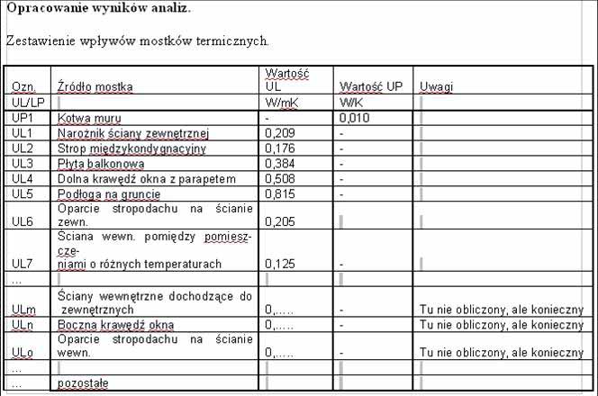
Determination of the final value of the U heat transfer coefficient for individual partitions.
attention: When determining the final heat transfer coefficient for a given partition in its full range or in a limited and strictly defined range, only the values of the bridges occurring in a specific range of a given partition are used in the formula below..
E.g. if we take into account the corner of the external walls, but we only count one of the faces to this corner (and both walls are of identical construction) we take 50% Ul1 values. For the corner of walls of different design, the influence of the corner should be determined separately for each of the walls by separating the internal environment.
So in the case of:
– corner of walls of various designs;
– walls and ceiling;
– walls and flat roof;
– walls and window and door joinery;
– floors on the ground;
-internal wall between rooms with different temperatures;
-walls as above. going to the outer wall;
– other unbalanced models;
it is recommended to separate indoor environments.
U = U0 + { A (Uli * At the) + S Upj } / A W/m2K
U - heat transfer coefficients of the area under consideration;
U0 - heat transfer coefficients without taking into account the influence of thermal bridges;
Uli - the value of the linear heat transfer coefficient of the i-th thermal bridge occurring in the area under consideration;
Upj - the value of the point heat transfer coefficient of the j-th thermal bridge occurring in the area under consideration;
A - the net internal surface of the partition in the area under consideration.
In the case of calculating the weighted average heat transfer coefficient for a set of partitions of different design:
U = S ( U0i * To the + { A (Ulj * Lj) + ΣUki } ) / W Ai W / m2K
If it is necessary to convert the heat transfer coefficient, calculated in accordance with the art for the inner surface of the partitions, to the outer surface
U' = U * Aw / Az W / m2K
U '- heat transfer coefficient converted to the external surface;
U - heat transfer coefficient;
Aw - inner surface;
Az - the outer surface corresponding to the same area.
INTERESTING FACTS
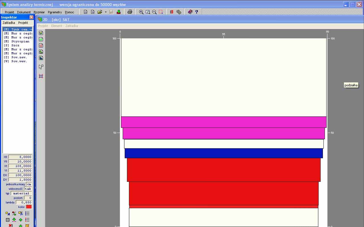
Sometimes it is necessary to analyze an arch wall. This is an example of a "permanent bridge" because the surface that absorbs heat from inside the building is smaller than the surface that transfers heat to the outside environment.. This situation can be modeled without much error in the form of a model composed of rectangles, as long as the correct proportions of internal to external surfaces are kept, and the wall structure in the intermediate range will be graded. The environment – the interior and exterior surfaces must only make contact with the respective surfaces without overlapping the side surfaces.
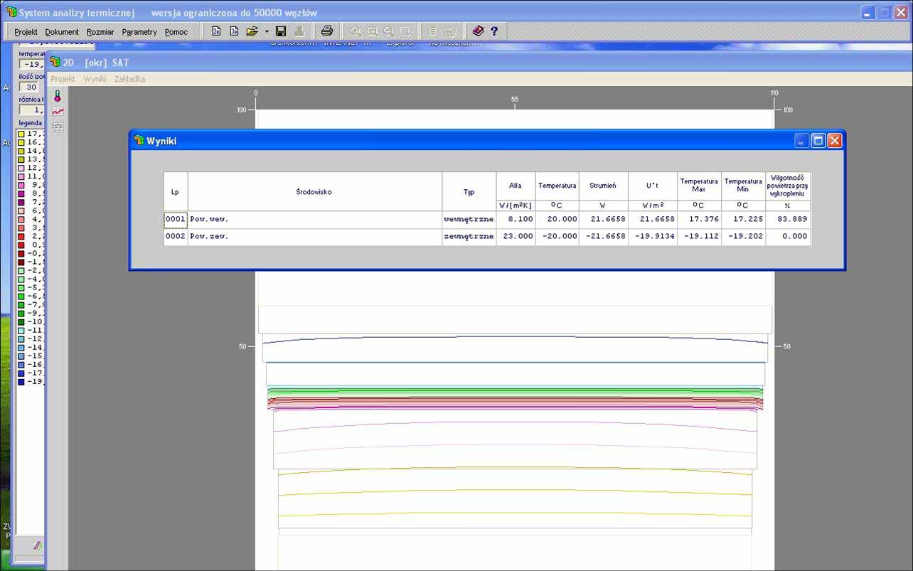
U0 okr = 21.6658 / 1.0 / 40 = 0,5416 W / m2K in relation to U0 = 0.5208 W / m2K of a straight wall
As is easy to guess, the curvature will be greater (shorter radius), the greater the heat loss due to the greater development of the heat transfer surface.
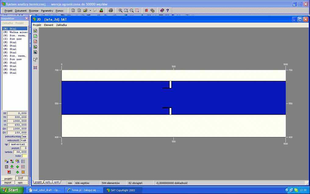
First example - "thermally tight" sandwich casing.
The base is a 150mm thick sandwich made of :
1mm of steel sheet λ = 58 W / mK
148mm of mineral wool λ = 0.04W / mK
1mm of steel sheet λ = 58 W / mK
One needs to know U0 = such a system
The given external environment ά = 21.89 W / m2K te = -10 degrees. C
The given internal environment ά = 8.13 W / m2K ti = + 20 degrees C.
U0 = 1/(1/21,89 + 1/8,13 + 0,148/0,04) = 0,2585 W / m2K
The plate was omitted as not influencing this result.
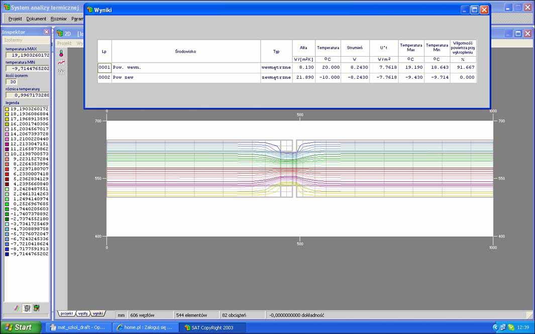
There is a linear bridge making a difference to the subway
(8,243 – 7,7545) [W/m2] * m =
0,4885 W/m
What gives
Ul= 0,4885 /30 = 0,0163 W / mK
You can also check, that there is no risk of condensation on the housing surface, because it will only happen at 91.667% air humidity.
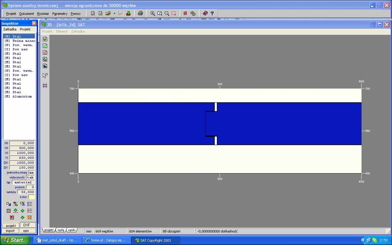
The second example - a sandwich casing with a construction defect.
In the second half of the 90s of the last century, there were systems such as in the discussed example.
Here, the ends of the metal sheets in the lock were connected with aluminum foil, wanting to create a vapor-tight system. The conductivity of aluminum has not been thought of. The foil is only 0.1mm thick, it is a very good heat conductor.
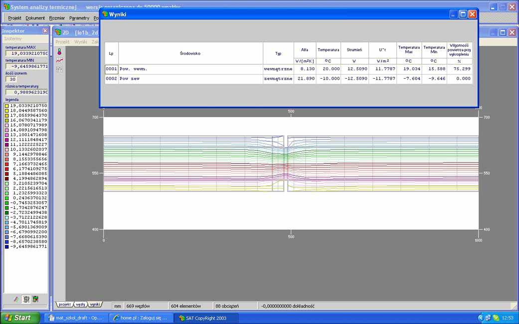
A stream was obtained 11,7787 W/m2
There is a linear bridge making a difference to the subway
(12,509 – 7,7545) [W/m2] * m = 4,7545 W/m
What gives
Ul= 4,7545 /30 = 0,1585 W / mK
This result clearly shows the deterioration of the system insulation.
Suppose, that the panels are 1.2m wide, i.e.. that every 1.2 m there is a linear bridge resulting from the system connection.
U=U0 + Ul / 1.2 = 0,2585 + 0,1585/1,2= 0,3906 W / m2K
As you can see, the air humidity at which condensation will occur on the inner surface has also decreased.
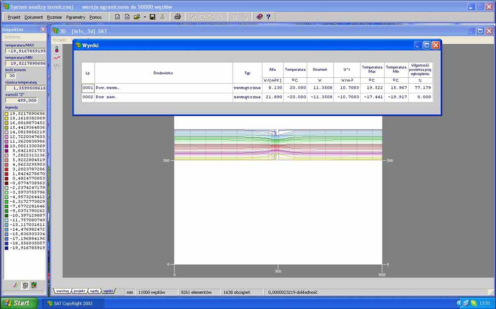
This is the U after considering only the "seams" of the system. In order for the wall structure to be durable, it must be screwed with bolts to the bolt.
Point bridges caused by screws must be taken into account.
The influence of the point bridge can be seen by observing the isotherms passing through the "bolt" and comparing them with a place distant from the bolt.
Up= (11,3508-8,2430)/30 = 0,104 W/K
This is the effect of a single fastener.
We are not developing the topic further, for it comes down to the same, what in traditional buildings, i.e.. recognition of all thermal bridges, a list of their heat flow coefficients and the calculation of the actual heat transfer coefficient for individual partitions.