Thermal bridges in energy certificates.
In November 2008 the year has been signed, long awaited by all interested in the subject of energy certificates, Regulation of the Minister of Infrastructure on the methodology for calculating the energy performance of buildings. One of the points of the regulation concerns thermal bridges. In this article, I will analyze the point 3.2.3 of Annex No. 5 and I will try to answer the question whether the recommendations presented in it can be directly implemented.
The above-mentioned point of the draft regulation was worded as follows:
„3.2.3. WsdustŁczybig strat ciepŁa prshez przenikanie nalezy obliczaex ze wzoru:
Htr = Ai [btr,i · (Ai · Ui + Ai li · Psi)] W/K (1.14)
gdzie:
|
btr,i |
wspOhŁczynnik redukcyjny oblijunniowej differentznicy hasperatur i–atj prshegrody (facingbl. 6); dla przegród aftermeędzy przestrshenią ogrshewaną i Wedodowiskiem shewnętrznym btr = 1 |
– |
|
Ai |
pole afterwierzchni i–tej przegrody otthey arecej prshestrzeń o regulowanej tinperaturshe, obnumberanej wg wymytrench shewnętrznych przegrody, (wymiary okien i drzwi przyjmuje się jathat wymiary otworthat w ścianie) |
m2 |
|
Ui |
wspOhŁczynnik prshenikania ciepŁa i–tej prshegrody pomeędzy przestrshenią ogrshewaon i stroną shewnętrzną, oblitimeny w przypadku przegród nieprsquintroczystych wedŁug normy PN EN ISO 6946, w przypadku okien, świetlicenters i drzwi przyjmuje się wedŁug Aprobaty Atchnicznej lub zgodnie z normą wyrobu PN–EN 14351-1; w odniesieniu do śtherean osŁitwych metalowo–szklanych wedŁug Aprobaty Atchnicznej lub zgodnie z normą wyrobu PN–EN ISO 13830, a w przypadku afterdŁbread already grandcie przyjmowany jako Ugr i obliczany jak w pkt. 3.2.4. |
W/(m2K) |
|
li |
dŁugośex i–tego liniowego mostka cieplnego |
m |
|
Psi |
liniowy wspOhłczynnik przenikania thereepŁa mostka cieplnego przylanguagety wg PN–EN 14683:2001 lub obliczony zgodnie z PN–EN 10211-1:2002 |
W/(mK) |
…
WsdustŁczybig przenikania linearych mosties ciepŁa yourzględnione we wzorze (1.14)
wyznalthougha się w oparciu o:
a) documententację techniczon budywings,
b) tablice mosties ciePLNand ch,
c) formczenia szczeheadline mostcenters ciePLNych.”
This point defines the basic parameter of the influence of the thermal insulation / conductivity of the building envelope on the heat loss to the external environment. So it is a basic size and should be strictly defined for a given building.
The first problem arises in the pattern itself (1.14). It's easy to see, that it does not mention point-type thermal bridges. I will try to look at the consequences of this omission. Traditional sandwich walls are connected with steel connectors - anchors. Let's assume, that there are 4pcs. anchors at 1m2. Let us assume the cross-section of a single anchor 25mm2. Anchor material - steel (or stainless steel).
Fig. 1. Cross-section through the considered wall.
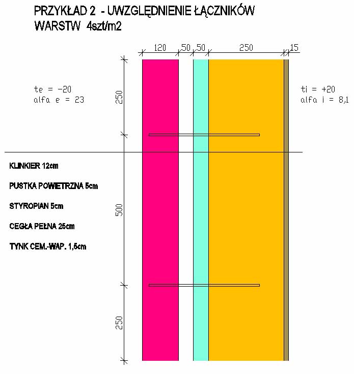
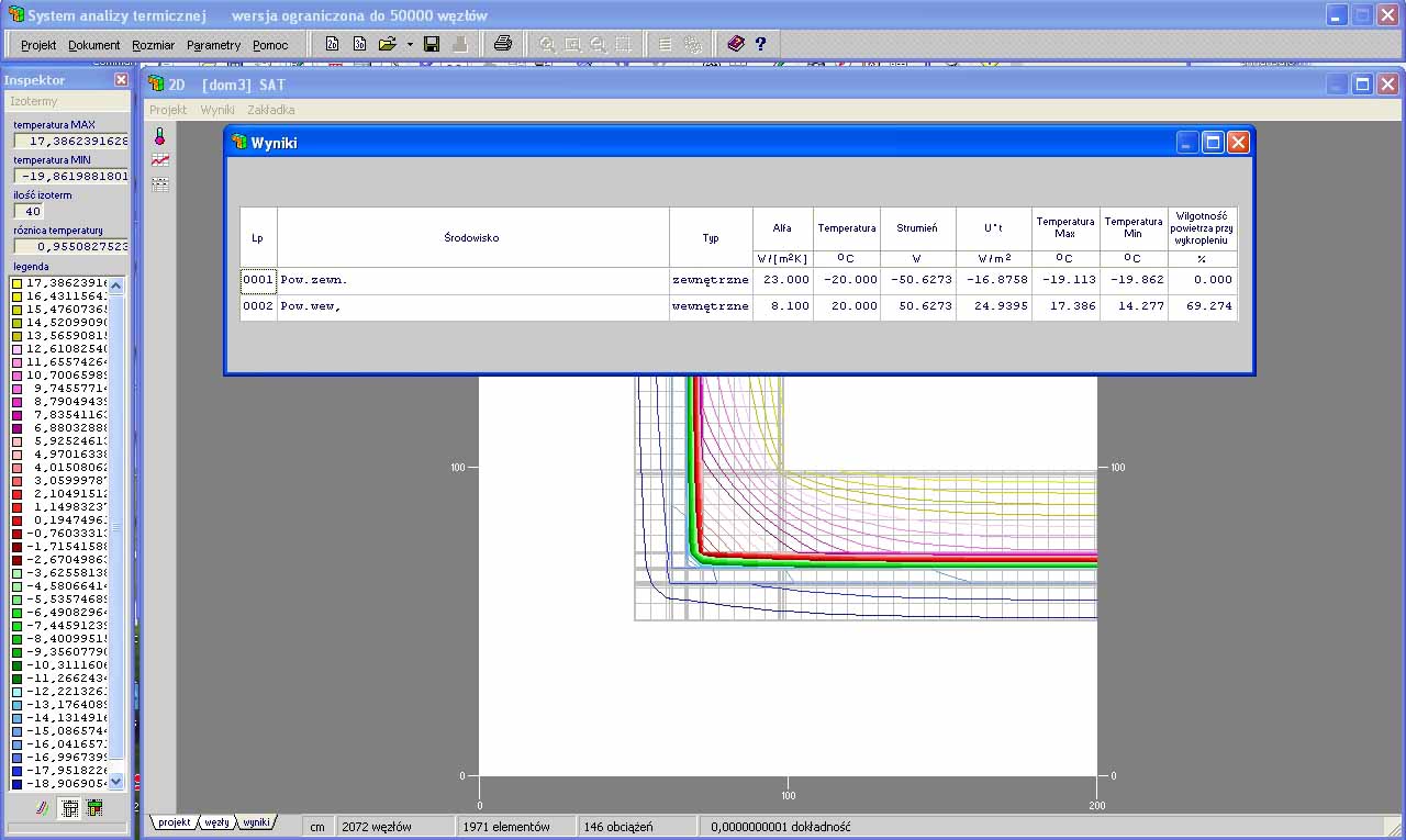
After creating the spatial model in the Thermal Analysis System program for the wall as shown in Fig. 1 with two steel anchors inserted per 1m2 (to simplify the model and shorten the computation time) we obtain (see Fig. 2):
U= 21,6014W/m2/40K= 0,5400 W/(m2K)
For the same wall, without taking into account the anchors U = 0.5208W /(m2K)
The influence of the two anchors is ΔU = 0.0192 W /(m2K) (x=0.0096 W/K)), what with 4pcs. anchors per m2 gives an increase in the heat transfer coefficient ΔU = 0.0384 W /(m2K) tj. o 7,4%. Suitable for stainless steel anchors (λ = 15W /(mK)) this increase will be 4,5%.
Taking into account other point or non-linear thermal bridges (spatial – complex) wzór (1.14) in this form it does not exhaust the problem. In my opinion, it should contain an additional component which is the sum of the effects of point and complex spatial bridges.
Lynx. 2. Calculation results using the SAT program.
 Others (from my point of view) the problem is the notation for Ai jako „pole powierzchni i-tej przegrody otaczającej przestrzeń o regulowanej temperaturze, calculated according to the external dimensions of the partition, (the dimensions of the windows and doors are taken as the dimensions of the openings in the wall)”. The imposition of an outer surface as obligatory for determining the effect of thermal bridges seems to be unfortunate. Let us assume the corner of the building to be constructed as before (Fig. 3).
Lynx. 3. Building corner calculation results.
A stream of 50.6273W flows through the 2D model corresponding to the situation in Fig. 3.
We calculate the linear heat transfer coefficient – Psi w stosunku do powierzchni wewnętrznej (internal surface length across the line of the linear bridge 2.03m):
Psi =50,6273W/m /40K – 2,03m * 0,5208W/(m2K) = 0,2085 W/(mK)
We calculate the linear heat transfer coefficient – Pse w stosunku do powierzchni zewnętrznej (the length of the outer surface across the line of the linear bridge is 3.00 m):
Pse=50,6273W/m /40K – 3,00m * 0,5208W/(m2K) = -0,2967 W/(mK)
As you can see, the entry in the project is unfortunate, because when counting on the outer surface, e.g.. in the corner, we obtain a negative value of the linear thermal conductivity coefficient. The same situation will apply to inter-story ceilings based on external walls, flat roofs, internal walls etc..