Concrete and reinforced concrete
The problem with thermal computing in the form of 2D and 3D numerical models is this, that they give results that exactly match the entered data. In other words, are prone to factual and logical errors of the program operator. The operator relies on the data available to him. These are usually standard sources, textbooks, certificates etc.
Looking for data on the thermal conductivity coefficient "λ" for reinforced concrete, You can find the data as below. This is an excerpt from a reprint of the 1999 standard. An even older standard, i.e.. 1984r. I couldn't find any other data while browsing the Internet.
Lynx. 1. Data for concrete and reinforced concrete found on the Internet.
| material name | Dry density (mean) kg/m3 | Thermal conductivity λ [w / mK] | |
| Medium humid conditions | Conditions damp |
||
| Plain concrete, reinforced concrete | 2500 | 1,70 | 1,80 |
Concrete is a relatively homogeneous material and can be accepted, that for a given density and type of aggregate, it will have the same thermal conductivity in each direction and for each sample. Entering a parameter for it in the table above is not a mistake.
Dopiero PN-EN standard 12524 distinguishes between concrete and reinforced concrete and gives the values of the thermal conductivity coefficient for (on the basis of tab. 1 str. 4 PN-EN 12524):
reinforced concrete in the degree 1% 2,3W/(mK)
reinforced concrete in the degree 2% 2,5W/(mK).
Reinforced concrete is a conglomerate of a steel skeleton and concrete filler. So since the concrete used in reinforced concrete shows the value of e.g.. λ=1.70 W/(mK), stal λ=50,00 W/(mK), replacement heat conductivity coefficient, it will be the result of the cooperation of both materials and their quantitative proportion as well as the reinforcement cover.
In order to present the dependence of the "λ" coefficient on the direction of heat flow and the amount of reinforcement, we performed a series of 3D calculations (three-dimensional) sections of reinforced concrete slabs and a column. The results confirmed the assumptions, that the value of the thermal conductivity coefficient increases with the amount of reinforcement (the degree of reinforcement).
The calculations were made with assumptions:
– concrete thermal conductivity coefficient λ = 1.70 W /(mK);
– thermal conductivity coefficient of reinforcing steel λ = 50.00 W /(mK);
– 30mm reinforcement cover
Tab.1.
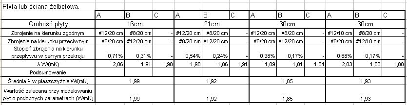
A - column for the direction consistent with the main reinforcement;
B – column for the direction of distributed reinforcement;
C - column for the direction perpendicular to the partition plane.
You may be tempted to create a simple recipe for calculating the thermal conductivity coefficient and checking it, whether this recipe will match the results above.
We have the basic conditions:
dla μ=0,0% λ=1,70 W/(mK);
dla μ=100,0% λ=50,00 W/(mK);
We assume a rectilinear course (not arguing, that is right).
λ ’= 1.7 +(50-1,7)/100* μ = 1,7+0,483 * m [1]
What gives for
0,71% λ ’= 2.04 during, when we know that λ = 2.06 error 1,0%
0,31% λ ’= 1.85 during, when we know that λ = 1.91 error 3,1%
for the mean value
0,51% λ ’= 1.95 during, when we know that λ = 1.99 error 2,0%
0,54% λ ’= 1.96 during, when we know that λ = 1.98 error 1,0%
0,24% λ ’= 1.82 during, when we know that λ = 1.86 error 2,2%
for the mean value
0,39% λ ’= 1.89 during, when we know that λ = 1.92 error 1,6%
0,68% λ ’= 2.03 during, when we know that λ = 2.03 error 0,0%
0,17% λ ’= 1.78 during, when we know that λ = 1.83 error 2,7%
for the mean value
0,43% λ ’= 1.91 during, when we know that λ = 1.93 error 1,0%
Let's substitute values from PN-EN for this relationship 12524.
1,00% λ ’= 2.18 while, when by. norm λ = 2.30 error 5,2%
2,00% λ ’= 2.66 while, when by. standard λ = 2.50 error 6,4%
All errors created in this way are smaller than the parameter used for reinforced concrete as for concrete. Why, however, the difference increases in relation to the standard value. This is why, that an averaging was assumed for a certain reinforcement interval and for different densities of the concrete itself. I would like to note, that in the table is given:
concrete arms 1% steel with a density of 2300 kg / m3
concrete arms 2% steel with a density of 2400 kg / m3.
It is not known exactly what density we are talking about - concrete itself cooperating with steel, or concrete and steel together. You should assume, that the concrete itself, because reinforced concrete cannot have a lower density than unreinforced concrete.
Additionally, we only work with plate elements with a specific cover and two-way reinforcement. The columns will show different properties due to the different nature of the reinforcement. The standard applies to all reinforced concrete structures without going into details. This is a very large averaging.
We sensitize, that the thermal conductivity of reinforced concrete can be much greater than that of concrete, which has been proven. When we consider the simple case of a wall without thermal bridges (apart from the reinforcement itself, which constitute internal thermal bridges of reinforced concrete in relation to concrete), it is of much less importance, because in any case, walls or ceilings, layered partition (with warming) it will be more resistant to insulation than to reinforced concrete. Sometimes the thermal resistance of the floor can even be neglected, or a reinforced concrete wall in the calculation of the total resistance.
This works to the advantage of the parameters of the newly designed building, at least it distorts the result a little. However, when we count 2D or 3D models with reinforced concrete thermal bridges or of another nature with the participation of a reinforced concrete structure, neglecting the influence of reinforcement on the thermal conductivity of reinforced concrete leads to significant errors. In such cases, the standard values of the thermal conductivity coefficient of reinforced concrete should be assumed or, based on a specific reinforcement and its arrangement, precise 3D models should be built, taking into account the reinforcement. Unfortunately, the latter method is very time-consuming and requires a lot of computer memory.
The standard averages the thermal conductivity in all directions. In the case of expert opinions, it is often necessary to determine the causes of freezing in a given place, near the beams, lintels, columns or perimeter beams. In such cases, it is important to determine the appropriate parameters for each direction of heat conduction.
I recommend interpolating the standard values (e.g. pattern similar to [1] although these will not be strictly true values, or linearly between two degrees of reinforcement specified by the code), because the standard gives us no other tools.
For the ceilings and walls we have analyzed, conclusions can be drawn, that the mean value "λ" of both directions in the plane is close to the value "λ" in the direction perpendicular to the plane. Therefore, it is not a great mistake to take an average value – the code as a value valid for all three directions in 3D models.